Thursday, 20 April 2017

leak testing of die cast parts

Quite often we see the requirement of leak proof parts from our customer. There are some specifications mentioned in drawing & may be some in the product specification sheet that our customer provides at the time of development.
However it has been observed that the die caster is not always very much aware of this process & theory behind the leak proof parts and thus it takes a back seat when actual development work takes place. As a result we encounter customer complain about the leak that takes place while in final assembly & testing at the customer plant or in some cases failure is reported from field.
As a die caster we must have an good understanding about what leak testing is all about & what measures we should take to ensure "0 PPM" parts to customer.
What is Leak
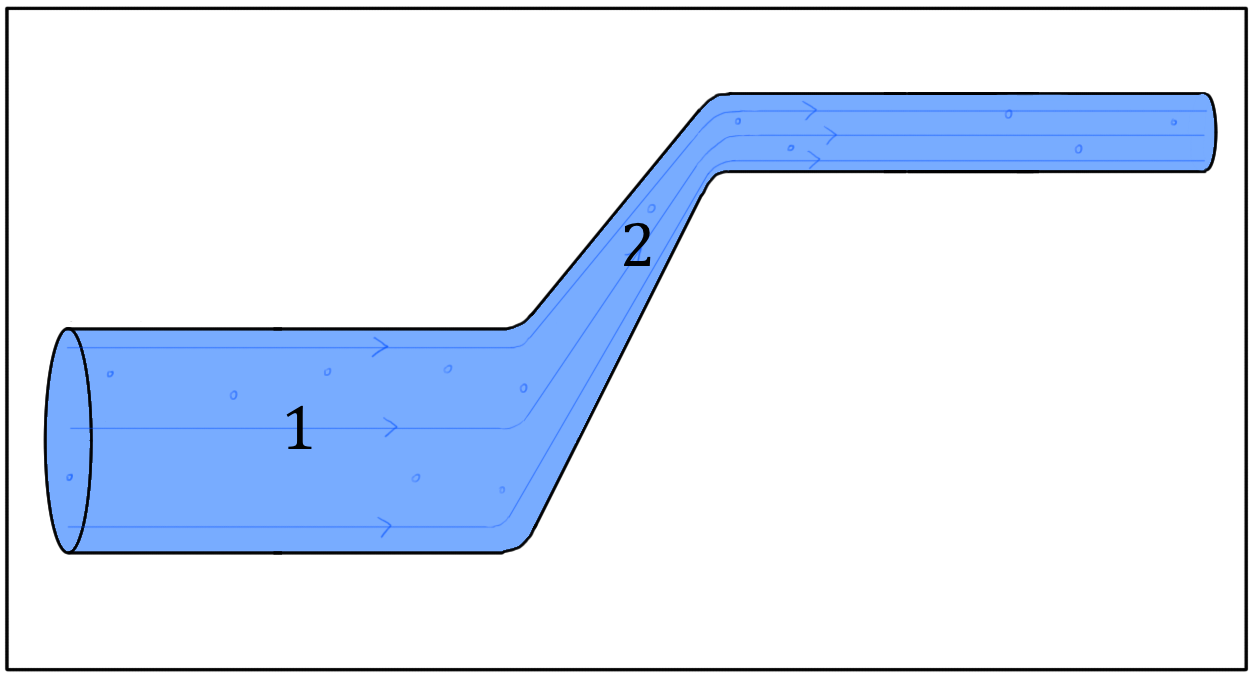
A leak is a flow of gas (or liquid) through the wall of a component (via an imperfection such as a hole, crack or bad seal). Leaks require a pressure difference to generate the flow; they always flow from higher pressure to lower pressure.

Leaks takes place from positive pressure (inside an component) to outside (at atmospheric pressure). Also a leak could be from atmosphere to inside an evacuated component, in both the cases we can see there are some flow of gas or liquid from one stage to another. 
How the leak rate is measured
For leaks of air into atmosphere, units are usually expressed as mm3 or cm3 (cc) per second or minute. So 16.6 mm3/sec = 1 cm 3/min. A bubble under water is about 30 - 50 mm3, so 1 bubble per second is about 30 mm3/sec or 2 cm3/min roughly. A standard unit of leakage which takes account of air pressure is the mbarl/sec. (Millibar-litre per second). A leak into atmosphere of 1 mbarl/sec is equivalent to a volume leak of 1000 mm3/sec.
Leak testing methodology
Key questions at the start of any leak test requirement are:
  • What size is the component and what is it’s internal volume?
  • What is the leak limit
  • Are the parts clean and dry, free from dirt etc:?
  • Is there access to inside geometry or is it a sealed unit?
  • Is it rigid or flexible?
  • Are parts at ambient temperature during final applications?
  • What is the surface finish of any sealing surfaces?
Test methods
Considering the various leak rate the test methods also varies to capture leak rate as per the requirement. Following are the methods adopted for capturing leak rate as per the specifications.
Flow rate defined as  -  10-9  - 10-3
By High volume Helium
Flow rate defined as  -  10-2  -  5
Air decay test - water submersible, Dunk test, Bubble leak test, Dry test
Pressure / vacuum method - The test piece and the reference volume are simultaneously pressurised (or evacuated) to a preset pressure. The air in the system is then allowed to stabilise, with the supply valves all closed. The Differential Pressure Transducer is automatically zeroed. After this stabilisation time, the pressure change in the test piece is compared to the pressure change in the reference volume, using the Transducer. If the test piece is leaking, the difference will increase and be measured, an alarm limit may be set for a pass/fail decision. The sequence is fully automatic, the accuracy and sensitivity of the system is defined by the method of setting the preset pressure together with the quality and type of control valves and Differential Pressure Transducer.
Helium systems. A vacuum pump evacuates the test chamber and test piece simultaneously to a preset vacuum. At this preset level, the chamber and the test piece are isolated and the chamber evacuated further to a very low pressure. A positive pressure variation is therefore created between the test piece and the chamber. Helium gas is then introduced into the test piece, often in a 10% concentration. A Mass Spectrometer analyses a sample from the chamber as the vacuum continues to be drawn. The Mass Spectrometer measures the helium leakage and sets the pass/fail decision. The test piece pressure is often compared to the chamber pressure before dosing with helium, to avoid saturating the Mass Spectrometer in the event of a gross leak.
High pressure air decay testing (over 6 bar)
The differential testing of parts with higher pressures poses additional challenges for leak testing.
Generally, the high pressure is not suitable for making accurate leak test calculations as it is too unstable.In these cases one arranges for the test volume to be on the opposite side of the leak path and the instrumentation is arranged to use the differential pressure rise. Parts are placed into a chamber possibly with infill pieces to reduce the test volume as much as possible. With this setup, the internal volume of the test piece can be pressurised to high pressure whilst the test system monitors the pressure in a volume outside the part
Low Pressure air decay testing (0 to 6 bar)
  • Offers the lowest cost solution
  • Simple to understand results data
  • Direct value results
  • Direct calibration
  • Temperature dependent process (alternative test method is vacuum
  • Best used when component under test is stable
The die caster must consult the leak testing machine manufacturer the detail requirement & repeatability of the machine function must be ensured. Also if required the testing must be conducted in controlled environment. also the cleanliness of  component, the tank condition, water quality, seal conditions must e monitored in periodic manner.
Happy leak testing.


Thursday, 23 March 2017

CASTING CHARACTERISTICS OF ALUMINUM DIE CASTING ALLOYS

CASTING CHARACTERISTICS OF ALUMINUM DIE CASTING ALLOYS.

Casting characteristics of an alloy are those properties of the alloy that characterize the alloy’s behavior in the casting process. The casting characteristics that should be considered in a die casting process are the tendencies of the alloy towards die soldering, hot tearing, and forming sludge, the alloys fluidity (flowability), machinability, porosity formation, macrosegregation, and feedability. 
We have many variety of alloys (Aluminum alloy) designated in standard EN1706 for high pressure die casting applications. However if we see critically those alloys are developed mostly on the basis of their applications & emphasis is given on their physical properties like tensile strength, yield strength, elongation, hardenability etc:. Those properties are very much essential to meet the product requirements. But as a die caster we also need to see the casting characters of those alloys. The reason behind such need is to see how best we can contribute to produce a better quality casting with optimum cost & best productivity. If you see what is mentioned in first paragraph (bold letters) regarding the casting characteristic, then you will obviously agree that as a die caster those are of utmost importance to cast an alloy in an efficient way. 
A very common process fault that we envisage in daily shop floor practice is "Die Soldering" & "Sludge formation". We will try to understand why such defects occurs & what kind of counteraction is required to minimise those problems. In doing so we will concentrate mainly on the alloys & their casting characteristics to understand the causes. We can see that such characteristics are very critical & contribute a lot to those defects. Eventually by controlling such critical issues we can actually control our rejections & enhance profit. As I mentioned in my early publications that three major contributor for a good casting are "Metal, Die & Process". In today's discussion we will focus on two problems "Die Soldering & Sludge formation" related to Metal (Aluminum alloy).
Soldering often occurs between aluminum alloys and ferrous die material and is a major problem in die casting. Sludge usually forms in aluminum die casting alloys and settle to the bottom of holding furnaces, thus reducing furnace capacity, and when entered into the casting cavity, causes hot spots in die cast components. Die castings may have machining problems caused by hard spots that are formed by entered sludge particles, and also because of the relatively hard surface layer caused by the fast cooling at the surface.

DIE SOLDERING
Die soldering is referred to the phenomenon that molten aluminum sticks to the surface of the die material and remains there after the ejection of the cast part. In die casting a challenge is to minimize the cycle time of the casting process to increase productivity and lower operational costs. Die soldering is an impediment to this challenge in that it leads to malfunctioning of die inserts that require replacement or repair, thus causing significant decrease in productivity. So, it is a major concern in the die casting industry. Die Soldering is the result of an interface reaction between molten aluminum and the die material during the impact of the high-velocity molten aluminum onto the die surface and the intimate contact between alloy and die at high temperature. The high velocity destroys the protective film (coating and lubricant) on the die surface. Here, the molten aluminum comes in contact with the virgin die surface. Subsequently, iron in the die dissolves into the molten aluminum and a layer of intermetallic phases is formed. This we call soldering in die, which is difficult to prevent.It has been found that soldering occurs more frequently around the gate where conditions of high temperature and high melt velocity exist. It is also observed that soldering takes place in thin section of die geometry & around the small core pins specially when located near the gate area. It has been observed that the mechanism of soldering is purely based on the diffusion and chemical reactions of the elements in the die (solid) and the liquid metal. So basically we derive that soldering is a diffusion driven reaction – iron diffusing out of the tool steel into the molten aluminum and forming the intermediate layers.
Various die casting parameters have been identified as playing critical roles during die soldering. The dominant ones are: 
· Temperature of the metal and die. 
· Chemistries of casting alloy and intermetallic layers. 
· Die lubrication and coating. 
· The die design and operating parameters. 

Temperature of the Metal and Die - The temperature of the cast metal and the die surface plays a critical role in causing die soldering. High metal and die surface temperatures lower the surface hardness and make the die surface less wear resistant. This makes the die more susceptible to erosion. High temperatures favor the growth of intermetallic phases by increasing the diffusion rate of the atoms of iron and aluminum. High die temperature may also break the lubricant film, and decrease its ability of preventing soldering. Hence high melt and die surface temperatures facilitate soldering and they must not be too high. There should not be hot spots in die surface, or inside the core. Metal and die temperatures also should not be too cold to cause poor filling. The temperature of the melt is a critical factor in creating "Soldering" on the die surface. It is found that holding temperature of the melt at ~ 663°C could minimize the occurrence of soldering. The die preheating temperature must be between 180 to 220 C. Higher temperatures will result in the inadequate application of the lubricant. Lower temperatures might result in the formation of cold shut in casting. The die surface must be polished to a medium level finish with no irregular pattern. A mirror polished of die surface enhances die soldering hence not recommended.

Chemistries of casting alloy and intermetallic layers - On reviewing it can be inferred that the formation of the intermetallic layers is purely based on the diffusion and chemical reactions of the elements in the die (solid) and the liquid metal. Experienced aluminum die casters have observed that different grades of aluminum alloys differ from each other in their tendency towards soldering. It is found that  zones of intermetallic compounds consisting of Fe2Al5, Fe3Al and FeAl3 phases (Aluminium Ferite). However, the presence of other alloying elements in aluminum alloys such as Si, Cu, Mg, etc., resulted in the formation of a number of complex intermetallic compounds in the intermediate layer, which actually plays a very insignificant roles in Soldering. It is established through research that higher tendency of Soldering is witnessed in the hypoeutectic Al-Si alloy, & the Al-Si-Cu, and the eutectic Al-Si, which has the least soldering tendency. This happens because of the presence of increasing amounts of silicon in the aluminum decreases the growth rate of intermetallic layers. Iron content in the casting alloy plays a critical role in causing soldering. 
Iron content in the casting alloy plays a critical role in causing soldering. The maximum solubility of iron in aluminum is 1.8 % at 650°C and 3 %, at 700°C. The soldering phenomenon diminishes as the iron content approaches this value. Also, the iron content influences the growth of intermetallics, which has a direct influence on the soldering. It is  found through research that the soldering tendency of an alloy with 0.8 % iron is high, and that of an alloy with 1.1 % iron is very low. This is because as the iron content in the cast metal reaches its saturation level the chemical potential gradient is greatly reduced. The amount of free silicon is high at the intermetallic layers because silicon breaks free from the casting alloy at the die interface and exists as large silicon crystals in the soldered microstructure. Aluminum alloys greater than 12 % silicon have a high propensity to form hard Si particles. So we can conclude as under for the intermetallic layers

  1. Higher Silicon will facilitate to reduce the intermetallic layers thus will reduce the die soldering 
  2. Aluminum alloys containing high iron content should have a limiting range between 0.9 and 1.15 percent by weight. Any excess Iron will facilitate die soldering.
Die Lubrication and Coating - The main propose of applying a lubricant or coating is to create a partition between the metal and the die surface. They reduce the soldering tendency by preventing contact between melt and die. Lubricant also assists melt flow and casting release. To effectively separate the melt from die surface the lubricants should form a film on the die surface. This film should be firmly attached on the die surface and be strong enough to resist the melt washout and the attack of melt heat. The film should also be uniform and continuously cover the entire die surface, especially the area, where the soldering is prone to occur. The lubricants tend to breakdown at elevated temperatures. To successfully apply lubricants onto the die surface, the die surface temperature should not be too high; otherwise, the heat breaks down the emulsion, and evaporates the water in the spray, and thereby leaves the lubricant solids on the die surface. When the lubricant breaks down in any region, it may be washed off in high melt velocity areas such as in thin wall sections or at the gate surround and the aluminum liquid attaches itself to the steel die surface. When there is a hot spot in the die, the surface energy of the lubricant material tends to increase and hence, causes the lubricant to get detached from the die and to flow to regions, which are at lower temperatures. This exposes the die metal to the liquid alloy and results in soldering

The die design and operating parameters - Thick sections of the die are potential sites for die soldering. Coring out to reduce the excess metal will help reduce soldering. Formation of a thin film of soldering roughens that area of the die surface, and this roughness promotes further soldering. Once soldering occurs, there is a rapid build-up of the aluminum alloy layer over the soldered layer after subsequent shots. Undercuts from die manufacturing or die casting operations facilitate soldering. Insufficient draft is another major factor, which affects the soldering phenomenon. As a die designer one must keep in mind when selecting the gate area & gate thickness. This is a tricky area where designer must ensure free flow of metal as well as to ensure no excess heat in die cavity or critical die geometry is protected from direct hitting of metal flow.


SLUDGE FORMATION - This sludge is made up of oxides, such as alumina (Al2O3) and magnesia (MgO), and primary crystals that contain Al, Si, Fe, Mn, Mg and/or Cr. These oxides and crystals have high melting points and high specific gravities; therefore, they tend to accumulate on the floors of furnaces and thus reduce the effective capacity of the furnace. Moreover, when the sludge crystals are entrained into castings, they decrease the alloy’s fluidity and form “hardspot” inclusions, which make machining difficult and degrade the mechanical properties of the cast component. The formation of sludge may also increase the die-soldering tendency of the alloy because sludge crystals are composed mainly of Fe and Mn rich compounds and their formation causes a depletion of Fe and Mn in the melt. The oxides form during alloy melting and treatment. Studying and finding the measures to reduce these oxides implies mainly to deal with melting and melt treating operations. Sludge formation has been shown to be dependent on the alloy’s chemistry, melting and holding temperatures, and time. The  studied of sludging phenomenon has defined a sludge factor (SF) for Al-Si-Cu alloys. This factor is calculated from the Fe, Mn, and Cr contents of the alloys as follows,

Sludge factor (SF) = (1 X wt%Fe) + (2 X wt%Mn) + (3 X wt%Cr) 
It is found that the Fe, Mn and Cr contents of the alloy as well as the cooling rate significantly affected the morphology, quantity, and size of the sludge particles. It is also found that sludge did not form until a certain temperature was reached for a given Fe content and the sludge forming temperature depended on the Fe content of the alloy.
The study shows different criteria were formed and it may cause confusion in comparing the sludge formation tendencies for different alloy. Even for a given alloy the predictions are different from different studies. One study showed that for a given alloy there was a critical temperature at which sludge formed and grew at the fastest speed. In addition, the time duration at the critical temperature is very important for sludge formation.
So what the die casting engineer will do to control the sludge & subsequently the hard spot in casting? Few counter measures are found sustainable as under.

  1. Do not take the holding furnace temperature above 680 to 690 C
  2. Holding the melt for long in furnace will lead to formation of sludge & Hard spot.
  3. Check the sludge factor of every lot of Heat that you are receiving from alloy supplier.
  4. Melting & Holding on a same furnace having the same hearth will lead to hardspot.
  5. Change your crucible as per the schedule & also get it tested from time to time.
  6. Keep your pouring cup clean & properly quoted. 
  7. Do not remelt overflows & thin flashes in melting furnace.
  8. Keep the runner & biscuit free from dirt/oil & other contamination.


Saturday, 11 March 2017

Improving of surface finish of die cast components.
I have taken the reference from Mr.Jon Miller, Chicago White Metal Casting Inc:
One of the many challenges that a die caster face is the surface finish. The requirement of the surface finish varies form application to application & customer to customer. Therefore it is not possible to draw a significant standardisation for the surface finish or appearance of the cast part in general.
Majorly the parts which are visible to customer after it goes to market demands for very uniform & smooth finish, without any dark patch & non uniform shades. The parts which are not so visible to customer may have some relaxation, however it again depends on customer requirement. There are many ways to achieve such requirement which are purely subjective & customer dependent. In most of the cases to establish a acceptable quality the supplier must get the 'Limit Sample' duly approved by the customer for a ready reference. 
Below discussion will show some light on what are the means for achieving the desired surface finish & how the surface finish are correlated with process, product design & other manufacturing value chain. 
The large majority of die castings require specific coatings and finishes, polishing and/or painting. These processes are necessary to meet cosmetic/decorative appearance requirements, enhance wear resistance and/or provide a protective barrier against corrosion.
The final decision on any post-casting finishing operation should always be made in advance of die design and only after detailed consultation with your casting supplier’s engineering department. The design features of your part have a direct impact on achieving your precise surface finish specifications.
Superior as-cast cosmetic surface finishes characterize die castings produced by today’s advanced technology. In order to achieve optimal results at the lowest cost per part, early discussions are essential to clarify precisely how the part will mate with other components in the final product assembly. This analysis is as important to final surface finish quality as it is to meeting tolerance specifications.
Die casting section, which are hidden from view and cosmetically non-critical, can be considered for placement of the parting lines and gating. These features can create significant cost penalties if they are placed on a viewable, cosmetic surface of the parts. Likewise, a potential sink mark on a non-cosmetic surface can be largely ignored, or steps can be taken to overcome its possible appearance by wall redesign—for example, internal support features which will be invisible to the user.
While the exterior finish is dictated by appearance specifications, the specific surface preparation called for usually depends more on functional design features. Critical edges may require a shave trim, special polishing, a chromate coating and final painting. Specified tight-tolerance holes may call for acid etching or chromating followed by reaming, milling or boring.
The type and quality of the final finish are impacted by the geometry of the design of specific part features. Minor modifications of critical surfaces, edges and mounting features can lead to reduced costs with minimum surface preparation prior to application of a final coating.
Pre planning, well before the final component design is finalized, is the essential step. Design consultation on post-casting machining and surface finishing, prior to tooling design, die construction and die cast production, is the recommended course of action.
Design modifications to aid surface finishing quality are not always feasible but, when possible, they can greatly improve results.
Die Cast Part Edges: Part designs that hide trimmed edges within the final product assembly eliminate the need for post-casting edge polishing. Early consultation on cosmetic features assures proper placement of necessary parting lines to conceal trimmed visible edges.
Die Cast Holes for Machining: Countersinks (champers) or counter bores placed on holes assure the integrity of the surface edge of tapped holes. Leading threads will be protected from debarring or polishing.
Die Cast Mounting Features: Wherever possible, create raised “shoulders” on bosses that will receive painting masks; scuffing thus can be avoided on surrounding painted surface areas during fastener torquing and mounting of mated parts.
Die Cast Bosses: Include correctly designed gussets to improve die fill and avoid resulting sink marks on Class “A” surfaces. Short and stocky bosses are preferable to tall, thin designs to optimize metal flow and insure integrity of the feature.
Die Cast Corners: Use the maximum allowable radius for all internal and external corners to permit vibratory deburring media to reach all part surfaces. This design guideline for die cast corners of housings is also vital to assuring the complete filling of the die cavity and maintaining the integrity of the corners of the part.
Die Cast Surfaces: Subtle textured surfaces can be produced, as-cast, on selected areas of a component by special preparation of the die. These cast-in textures are created by photoengraving techniques during die construction and are sometimes recommended for use on the underside of complex parts to aid in the smooth filling of the die.
Depending on the specifications on durability, protection and cosmetic appearance, most aluminum, magnesium and zinc die castings will receive one to three post-casting finishing steps: deburring, conversion and/or combined conversion functional coating, and a final surface finish coating.
Post-Trim Deburring: Vibratory processes including automated operations using a range of media types, are used to round sharp edges, remove burrs, loosen flash and debris, and smooth and brighten surfaces. Liquid, selective media, calibrated vibration and special compounds can also be used to cushion against damage. Most die castings go through a mechanical deburring operation prior to post-trim finishing, though additional operations may be required for 100% burr-free specifications.
Surface Conversion Coating: Deburring is usually followed by a conversion coating to remove any remaining oil, diecast part release agents and other contaminants. Where final painting is specified, this coating serves as preparation and primer. In many non-cosmetic applications, this conversion coating serves as the component’s final finish.
Environmentally friendly Trivalent clear chromium is now a proven, economical alternative to widely used hexavalent chromium coatings, offering high corrosion resistance for aluminum, magnesium and zinc die castings. With a bright finish, it meets stricter EPA regulations and RoHS European Union mandates, avoiding concerns with prohibited toxic hexavalent chromates.
Combined Conversion Coatings/Functional Finishes: Where a diecast component has a specific functional requirement, such as added corrosion protection, added durability and/or semi-decorative appearance, one of the combined conversion-functional finishes is often recommended. A combined coating replaces the use of a surface conversion coating, which serves as either a paint base or the part’s final finish.
Final Cosmetic Surface Finish: While final painting or plating of diecast housings and components is most often specified for cosmetic purposes, and to sustain their decorative appearance over the life of the part, other functional purposes of a final applied finish may be of equal, or of even greater, importance. These include: maximizing corrosion resistance, heat dissipation, and surface performance under abuse, and adding greater insulation properties.
A wide range of painting applications is available for die castings in matching finished, mating parts produced in other production processes. These final finishes include powder coatings in finishes from fine to coarsely textured, liquid paint polyurethane and water-based finishes applied at various thickness/texture levels.
Component masking is an essential part of virtually all cosmetic surface finish applications and required to assure part areas that must not receive finish coatings are protected during processing. Required protective masks must be applied during finishing production and later removed. Costs are proportional to part complexity and the resulting masking required. Unique to diecast parts, special fixtures mated to the die castings can be constructed, in the case of longer finishing runs and those parts suited to such fixturing. If feasible, such fixture masks can reduce finishing production costs.
Painting (Powder or Liquid): Non-solvent-based powder coatings are environmentally friendly, enabling non-toxic waste disposal. Powder coatings for die castings produce a durable, uniform surface finish, from matte to semi-gloss, available in a range of surface textures. Custom colors can be formulated at extra cost.
Powder coating is the only recommended painting process for die castings operating in the field at temperatures above 300F (149C). Custom formulations are available to enable maintenance of coating integrity at even higher operating temperatures.
Polyurethane and other wet paint chemistries are the most common final color finishes for die cast components, and have now been joined by water-based wet paints. Finishes from matte to high-gloss are available.
Total production costs and lead times for most liquid paints are lower than for powder coating, especially for short production runs, particularly those projects requiring a custom formulation.
Electro-deposition of a metallic coating on a die casting can provide the most attractive, durable and wear- and corrosion-resistant finish of any surface treatment, at proportionately added cost. While die castings offer excellent built-in EMI-RFI shielding as cast, internal board design sometimes indicates additional plating to achieve maximum possible shielding protection.
Considering all that a diecast component must go through after the molten metal solidifies, purchasers and designers should work with casting suppliers early in the process to ensure parts move efficiently from the early stages of design through casting and post-casting processing. The final results will be higher quality, lower cost castings—something every casting purchaser strives for.  

Monday, 13 February 2017

Die steel properties & requirement

Die casting is an economical process to produce complex parts in aluminium alloy, zinc, copper etc:. in modern days time die casters are demanding higher production rate, very less down time & extended die life. In addition to this the complex & large die casting parts are extending the challenge to the extreme. Surely die casting dies becomes a crucial factor to meet such challenges.
The performance of a die largely depends on following factors, namely

  1. Good die design
  2. Good die steel
  3. Good Heat treatment of die 
  4. Good workmanship of die
  5. Proper maintenance of dies throughout the life cycle.
  6. Process parameter setting
  7. Product design
Today we will look into some of the aspects of die steel that are important to achieve good die life. 
The die is working as heat exchanger. When the hot molten metal is pressed in high temperature & high speed in die cavity the the die temperature shoots up immediately & as the solidifies cast part is ejected & die spray applied on die the temperature drops down significantly. This causes a thermal shock in die. Also when the molten metal runs through the cavity it creates a high friction with die material which causes Galling & Erosion of steel. Besides there are other severe working conditions which causes mechanical stress, thermal fatigue etc; on die steel. Therefore the die steel must be capable to withstand such severe working conditions & produce good quality castings with prolonged die life. 
Typically for die casting "Hot working tool steel" is recommended which falls in to the category of H11 & H13 grade of steel as per AISI grade. Let us have a look into the alloying elements these steel grades are made of.
H11 Grade - Carbon - 0.35 to 0.45%, Manganese - 0.2 to 0.6%, Phosphorous - 0.03% max, Sulphur - 0.03% max, Silicon - 0.8 to 1.25%, Chromium- 4.75 to 5.5%, Vanadium- 0.3 to 0.6%, & Molybdenum- 1.1 to 1.6%.
H13 Grade - Carbon - 0.32 to 0.45%, Manganese - 0.2 to 0.6%, Phosphorous - 0.03% max, Sulphur - 0.03% max, Silicon - 0.8 to 1.25%, Chromium- 4.75 to 5.5%, Vanadium- 0.8 to 1.2%, & Molybdenum- 1.1 to 1.75%.
From the above we can see that while "Mn" & "P", "S" are actually remains as a residue & other important elements are Chromium, Vanadium & Molybdenum apart from Carbon.
The hot working tool steel is characterized by 
  • Good resistance of abrasion both low & elevated temperature. 
  • High level of toughness & ductility
  • Uniform & high level of machinability & polishability
  • Good high temperature strength & resistance to thermal fatigue
  • Excellent through hardening property
  • Very limited distortion during hardening
Let us see how hot working tool steel get such characteristic & what are the contribution of key alloying elements.
Carbon - Carbon is essential in forming of cementite & iron-carbon martensite. The hardness of steel or more precisely hardenebility is increased by adding more carbon up to about 0.65%. Wear resistance can be increased by adding up to 1.5%. Martensite being the hardest of microstruture hence Carbon is an essential component in steel.
Chromium - This element has a tendency to increase hardness penetration. Chromium can also increase the toughness of steel, as well as wear resistance. With higher content of more than 14% this can resist stain & corrosion in steel. Steel with higher chromium is also having higher critical temperature in heat treatment.
Vanadium - This controls grain growth during heat treatment and helps increase toughness & strength of steel.
Molybdenum - This element increases the hardness penetration of steel, slows the critical quenching speed & increases high temperature tensile strength.
The typical die life of aluminum casting is varying from 50000 shots to 250000 shots in average, depending on various factors as mentioned earlier.
The die economy therefore largely depends on Raw materiel of the die. The tooling cost varies from 10 to 20 % of the component cost & out of that about 15% of the die cost is for the material. Hence choosing correct die material is very important for tool maker. 
Thee are many renowned die steel maker & one can choose the supplier depending the geographical location, availability & support provided by the die steel maker.

Sunday, 5 February 2017

Bernoulli's equation for die casting design

High pressure die casting is all about how best you feed the metal in the die cavity. we have molten metal & the die casting machine which is used to push the metal with high pressure & high velocity inside the cavity. The metal starts moving from the sleeve to main runner & then to sub runner & finally enter the die cavity through gate. Therefore we can understand that gate & runners are critical for quality casting, because this actually controls the flow of metal inside the cavity.
Before going to the design aspects of runner & gate in high pressure die casting, we have to understand how liquid metal behaves when it is pushed through the runner & gate with high pressure & high velocity. If we mastermind the property of fluid mechanics, it will be easy for us to arrive at a proper runner & gate design in die casting.
To understand the property of fluid we will go through the "Bernoulli Equation".
Fluid dynamics is the study of how fluids behave when they're in motion. This can get very complicated, so we'll focus on one simple case by Bernoulli's equation, but we should briefly understand the different categories of fluid flow.
Fluids can flow steadily, or be turbulent. In steady flow, the fluid passing a given point maintains a steady velocity. For turbulent flow, the speed and or the direction of the flow varies. In steady flow, the motion can be represented with streamlines showing the direction the water flows in different areas. The density of the streamlines increases as the velocity increases.
Fluids can be compressible or incompressible. This is the big difference between liquids and gases, because liquids are generally incompressible, meaning that they don't change volume much in response to a pressure change; gases are compressible, and will change volume in response to a change in pressure.
Fluid can be viscous (pours slowly) or non-viscous (pours easily).
Fluid flow can be rotational or irrotational. Irrotational means it travels in straight lines; rotational means it swirls.
We'll focus on irrotational, incompressible, steady streamline non-viscous flow on which the equation is derived at.
Bernoulli's equation is essentially a more general and mathematical form of Bernoulli's principle that also takes into account changes in gravitational potential energy. Let's take a look at Bernoulli's equation and get a feel for what it says and how one would go about using it. Bernoulli's equation relates the pressure, speed, and height of any two points (1 and 2) in a steady streamline flowing fluid of density rho. Bernoulli's equation is usually written as follows,
P, start subscript, 1, end subscript, plus, start fraction, 1, divided by, 2, end fraction, rho, v, start subscript, 1, end subscript, start superscript, 2, end superscript, plus, rho, g, h, start subscript, 1, end subscript, equals, P, start subscript, 2, end subscript, plus, start fraction, 1, divided by, 2, end fraction, rho, v, start subscript, 2, end subscript, start superscript, 2, end superscript, plus, rho, g, h, start subscript, 2, end subscript
The variables P, start subscript, 1, end subscriptv, start subscript, 1, end subscripth, start subscript, 1, end subscript refer to the pressure, speed, and height of the fluid at point 1, whereas the variables P, start subscript, 2, end subscriptv, start subscript, 2, end subscript, and h, start subscript, 2, end subscript refer to the pressure, speed, and height of the fluid at point 2 as seen in the diagram below. The diagram below shows one particular choice of two points (1 and 2) in the fluid, but Bernoulli's equation will hold for any two points in the fluid.
Bernoulli's equation can be viewed as a conservation of energy law for a flowing fluid. We saw that Bernoulli's equation was the result of using the fact that any extra kinetic or potential energy gained by a system of fluid is caused by work done from external pressure surrounding the fluid. You should keep in mind that we had to make many assumptions along the way for this derivation to work. We had to assume streamline flow and no dissipative forces, since otherwise there would have been thermal energy generated. We had to assume steady flow, since otherwise our trick of canceling the energies of the middle section would not have worked. We had to assume incompressibility, since otherwise the volumes and masses would not necessarily be equal. We have already mentioned itearlier before going to this equation.
Since the quantity P, plus, start fraction, 1, divided by, 2, end fraction, rho, v, start superscript, 2, end superscript, plus, rho, g, h is the same at every point in a streamline, another way to write Bernoulli's equation is,
P, plus, start fraction, 1, divided by, 2, end fraction, rho, v, start superscript, 2, end superscript, plus, rho, g, h, equals, c, o, n, s, t, a, n, t
This constant will be different for different fluid systems, but for a given steady state streamline non-dissipative flowing fluid, the value of P, plus, start fraction, 1, divided by, 2, end fraction, rho, v, start superscript, 2, end superscript, plus, rho, g, h will be the same at any point along the flowing fluid.
Bernoulli's principle can be applied to various types of fluid flow, resulting in various forms of Bernoulli's equation, there are different forms of Bernoulli's equation for different types of fluids. 
The metal that flows through runner, sub runner & gate obeys the Bernoulli's equation which states that total energy head remains constant. While design the runner & gate we should keep in mind that

  1. To minimize turbulence to avoid trapping of gas in cavity.
  2. To get enough metal in the die before the solidification starts
  3.  To avoid shrinkage
  4. Incorporate a system to avoid trapping of nonmetallic substances in casting.
So friends next time please make sure your runner & gate is designed in optimum condition in line with Bernoulli's equation.